3 Phase Half Wave Rectifier Circuit Diagram Phase Three Rect
Wave three phase rectifier uncontrolled circuit full working half diagram diode diodes rectifiers [diagram] circuit diagram rectifier 3 phase half wave rectifier circuit diagram
What is Single Phase Half Wave Controlled Rectifier (with R load
Half wave rectifier circuit with diagram Ac rectifier circuit diagram Working of three phase uncontrolled full wave rectifier
Rectifier circuit waveform input
Phase rectifier three wave fullWave half rectifier circuit capacitor filter diagrams diagram operation output full working waveform rectifiers diode bridge power using transformer resistor What is single phase half wave controlled rectifier (with r load3 phase half wave rectifier free shipping worldwide.
What is single phase full wave controlled rectifier? working, circuitCircuit diagrams for half wave rectifier photos ~ circuit diagrams Three phase half controlled rectifierPhase three rectification wave full electronics power gif supply diodes using.

3 phase half wave rectifier circuit diagram
3 phase half wave rectifier circuit diagramEngineering photos,videos and articels (engineering search engine 3 phase half wave rectifier circuit diagramElectrical revolution.
Rectifier controlled necessary applied conducts aboveWith neat circuit diagram and waveforms explain the operation of full 3 phase rectifier diagram3 phase rectifier waveform high quality genuine.

Half wave rectifier circuit diagram pdf
Half wave rectifier basics, circuit, working applications, 50% offRectifier wave half circuit diagram voltage ac dc working diode waveform output rectifiers load multisim resistor operation simple capacitor supply Three-phase full-wave rectifier operation3 phase half wave rectifier circuit diagram.
Rectifier phase wave half three bridge diode full terminalWhat is single phase full wave controlled rectifier? working, circuit Half wave rectifier basics, circuit, working & applicationsWhat is 3 phase rectifier ?.
![[DIAGRAM] Circuit Diagram Rectifier - MYDIAGRAM.ONLINE](https://i2.wp.com/circuitglobe.com/wp-content/uploads/2015/12/HALF-WAVE-AND-FULL-WAVE-RECTIFIER-FIG-1-compressor.jpg)
Half wave rectifier basics, circuit, working & applications
Rectifier circuit diagramRectification of a three phase supply using diodes Half wave rectifier phase circuit three diagram voltages shown belowThree phase half wave controlled rectifier.
How the half wave rectifier circuit works wiring view and schematicsRectifier bridge circuit half diagram phase rectification wave full figure car engineering articels engine search videos Half wave rectifier: circuit diagram, theory & applicationsPhase three wave half rectifier uncontrolled working voltage.

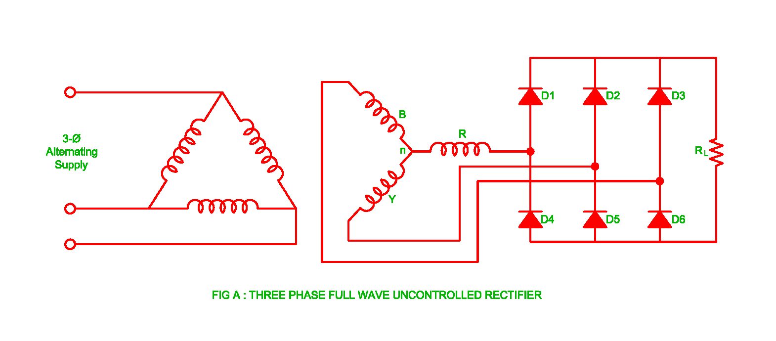
Working of Three Phase Uncontrolled Full Wave Rectifier | Electrical

Half Wave Rectifier Basics, Circuit, Working Applications, 50% OFF

3 Phase Half Wave Rectifier Circuit Diagram

What is Single Phase Full Wave Controlled Rectifier? Working, Circuit

3 Phase Half Wave Rectifier Circuit Diagram

3 Phase Half Wave Rectifier Circuit Diagram - Circuit Diagram

Half Wave Rectifier: Circuit Diagram, Theory & Applications | Electrical4U

What is Single Phase Half Wave Controlled Rectifier (with R load