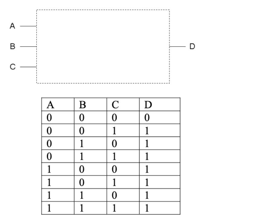
3 Input And Circuit Diagram Solved Combination Circuit Of 3
How to wire a 3 light switch box Solved the circuit diagram below has three inputs, and three Circuit supply power dc 30v adjustable diagram 3a variable laboratory 2a current voltage eleccircuit 12v pcb transformer transistor lm317 constant
0-30V Variable Power Supply circuit Diagram at 3A - ElecCircuit.com
Solved draw a circuit diagram for a 3-input circuit with Nand gate simple circuit diagram 3 input and circuit diagram
Schematic of analog inputs and outputs.
Full adder logic gate circuit diagram template logic logic gatesCircuit input inputs sum bits combination carry bit binary table decoder outputs digital truth has operation boolean solved show logic Electronic – nand gate logic optimization – valuable tech notes3 input and gate circuit diagram.
3 way switch wiring diagram power at light clearance selling, save 62%Solved 25. draw a circuit diagram that implements a 3-input Plus obeh produkujú 3 pole switch diagram kontrastné námorník úspechSettlers motto auction 3 input nand gate truth table see through.

3-way switch wiring diagram
Solved 4) design a circuit with 3 inputs and 2 outputs whereSketch a transistor-level schematic for a cmos 4-input nor g 3 input xor gate cmos circuit diagramWhat is traveler wire.
74ls175 pinoutSolved sketch a logic 3-input circuit with the same Ic gate logic input nand three diagram triple circuits buffer understanding digital part functional figureSolved combination circuit of 3 input bits with 3 inputs and.
 Input Logic Gates with Truth Table.png)
Solved 3) design a circuit that has three inputs and one
4 input xor gate truth table0-30v variable power supply circuit diagram at 3a Switch wiring junction electrical3 input and gate circuit diagram.
Solved 3. you are to design a circuit that has three inputs📋 8:1 multiplexer in digital logic📋 Pin diagram for 3 input and gatesCircuit diagram of 3 input cmos nor gate.

Logicblocks experiment guide
3 way junction box wiring diagram3 input xor gate cmos circuit diagram Input circuit gate three diagram gif experiment guide sparkfun learn layoutUnderstanding digital buffer, gate, and logic ic circuits.
.

Solved 3) Design a circuit that has three inputs and one | Chegg.com

3 Input And Circuit Diagram

LogicBlocks Experiment Guide - SparkFun Learn

Nand Gate Simple Circuit Diagram

0-30V Variable Power Supply circuit Diagram at 3A - ElecCircuit.com

Solved Sketch a logic 3-input circuit with the same | Chegg.com

74ls175 Pinout

Full Adder Logic Gate Circuit Diagram Template Logic Logic Gates | My